
I am powering a 5V microcontroller (arduino clone, atmega328p) using a 9V block and a buck converter. Now I want to let the microcontroller occasionally measure the battery voltage, so I can get an idea of how full it is.
My first idea was to use a simple voltage divider:
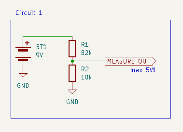
I’ve chosen the resistor values so that:
- the voltage at the measure output is
< 1.1V, to be able to use the 1.1V internal reference of the atmega’s ADC R1 || R2 < 10kΩ, since the atmega datasheet says “The ADC is optimized for analog signals with an output impedance of approximately 10 kΩ or less”
This is great and all, but what bothers me is that this circuit will constantly draw ~100µA from the battery.
So, my next thought was to add a mosfet to the divider, to switch it on only while measuring:
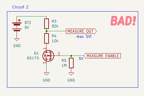
This is obviously bad, because now when the mosfet is off, the ADC input sees the whole battery voltage.
To address that issue, I’ve added a second mosfet into the measure path:
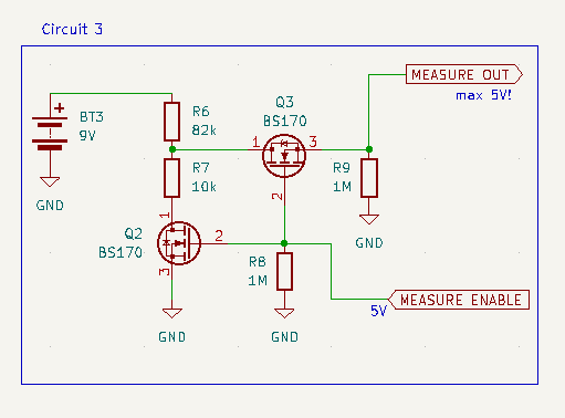
This works, and it does not draw any current, except while measuring.
However, it’s quite a few parts. So I’m curious if anyone has an idea how to do this with just a single mosfet. It seems to me like it should be possible, but I haven’t figured out how.
Oh, and if I’m doing something stupid here, please tell me :)
Could you do similar to diagram 2, but instead of an N-FET use a P-FET between the battery and first resistor in the potential divider?
Add a gate pull up resistor to source to ensure the FET is off by default, have the micro pull the gate down to take a measurement. You’ll probably need to add another resistor on the control pin to 0V to limit the voltage there also, but those two can be much much higher values to really limit current. Or use a zener/TVS diode instead of second resistor to clamp the voltage instead of dividing (more robust).Switch it with an NFET
The micro will see 0V or divided/clamped battery voltage on the measurement pin.
That’s a great idea! Unfortunately I don’t have a P-FET lying around, so cannot try it right now.
Not sure I understand this point. Which resistor would you replace with a diode?
Sorry, I think I was talking nonesense (doing this in my head and just woke up 😅).
Not sure it’ll work with just a P-FET actually. You’ll likely need to control the PFET with a NFET, otherwise you still end up with too high a voltage on your control pin when the FET is off due to the gate pullup (unless you can use a fet with a very high Vgs Threshold and then drive it push/pull from the micro, but this isn’t really best practice).
The above comment about diodes was to protect the microcontroller pin, but you end up not being able to control the FET doing it that way.
I think either your existing Option 3 or PFET upstream of the divider, switched via an N-FET is the way to go.