

Hello fellow friends of Console Repair!
Today I’d like to ask for some ideas about an old Game Gear (the first one I ever recapped) as it is showing the “red light for one second and off” issue.
Basically, as this was my first attempt (and a successful one) at recovering a Game Gear, I knew I did not clean the board too well or properly removed solder before changing caps, so when I saw the issue, I removed all the caps, cleaned the board and changed the caps again for good measure. Still, the issue is still there.
So here is my fruit of my troubleshooting afterwards:
-
the voltages from the power board are correct (I tested as well with the working power board of another VA0 I have around, no change). And all the capacitors are of the correct value and polarity.
-
the issue seems related to the VBat circuit as I observed that:
- R50 receives around 13V from the power board, which seems the rough amount expected when powering from the wall adapter.
- R50 ends with just 0.90V - however, removing the resistor (it’s a 9.1K one), and testing with a multimeter, provides 9.01K, which is good enough, and definitely not something that would kill the voltage that much
- as we get 0.90V from R50, the other resistors just reduce the voltage even more. I removed R51 and R52 and they both tested well on the multimeter (2.98K for the 3K one and 1.09K for the 1.1K one).
-
I thought that the diode D4 might be faulty and replaced it, but in reality it seems it was just dirt, anyway, it’s a new one now…
-
VRef at the power board outputs 1.26, but it arrives to the ASIC as 0.30V.
-
Finally, as part of the troubleshooting, I noticed that removing C49, the system works fine… After the removal of C49 all the voltages that were too low becomes higher, in line with the ones of the other working Game Gear.
So here my doubts that I hope someone might help me clarify:
-
What could affect VRef as in principle is directly connected from the power board to the ASIC? Following the schematics here, I don’t see anything that should interact with the circuit, modify the current. Still, the removal of C49 normalizes the voltage to around 1.25V…
-
what could be the reason why the voltage drops when the capacitor C49 is installed?
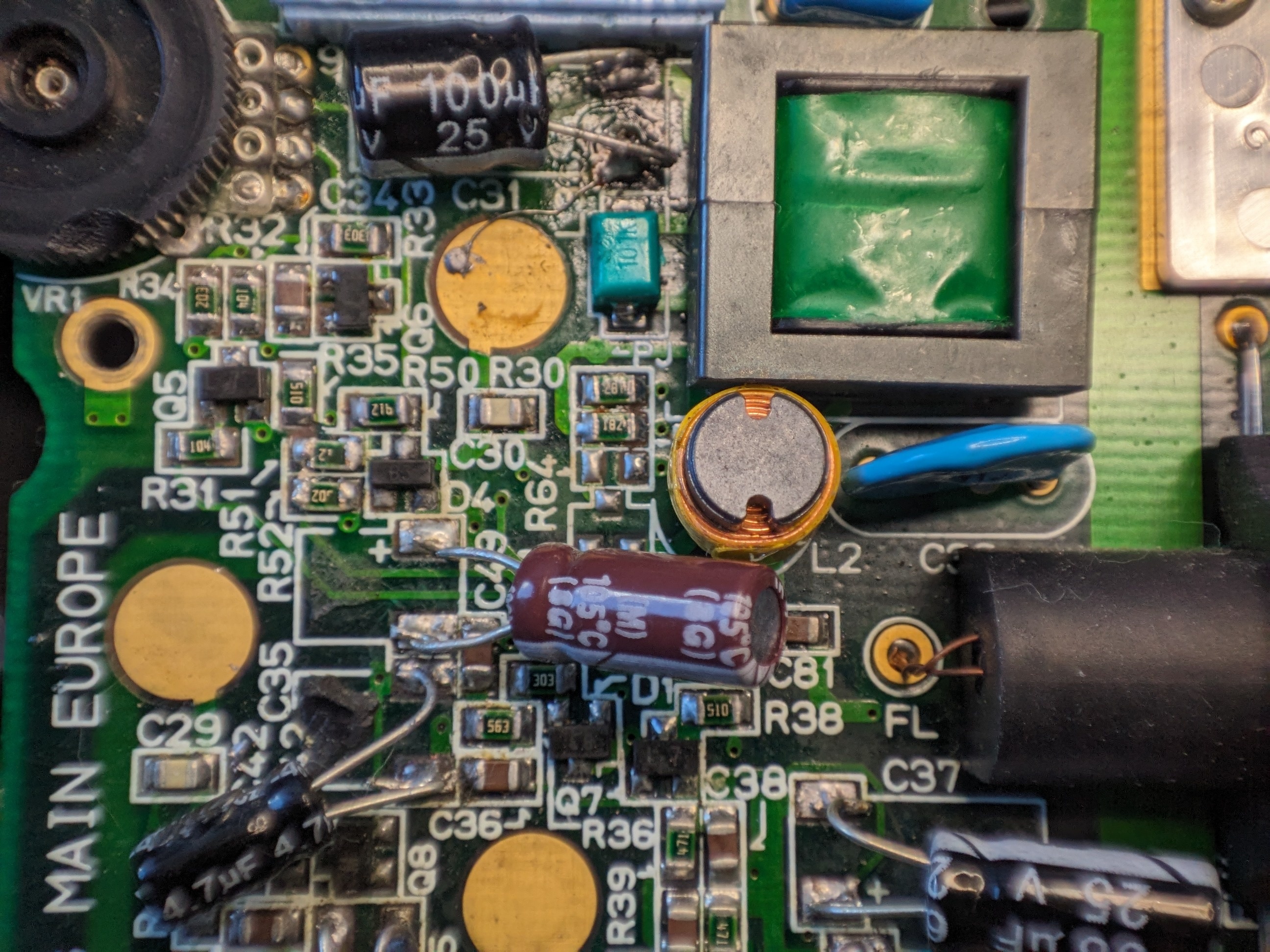
I think it might be useful to share a couple of pictures of the relevant parts of the board, but I can share more, if needed.

Did you ever figure it out? I spent some time puzzling over your post, wondering if you managed to spot a difference between the other working GG and the one that operates when the cap is removed??
No, I didn’t. But I suspect that there might be some unwanted bridge somewhere which is directing electricity where is shouldn’t and lowering the overall voltage in that part of the circuit.
I had no time yet, but I was thinking to remove the components of that part of the circuit and solder them onto an external board one by one. If I reach a point where the circuit starts working, I should then see if the last component moved was shorted with another one.
It will take a while, but I’d like to keep searching for the answer until it’s found :)