Here’s a close up picture of the print itself: https://imgur.com/a/flJjhGs. It’s printed in PETG with 40% infill. I printed it first in PLA, but then it snapped immediately (thankfully not on my face). The only reason why I didn’t use PETG from the get go was that I actually didn’t know you could print it without an enclosure.
One thing that I don’t like about this setup is that I’m missing a degree of freedom. If I tilt the monitor upwards, it will also tilt a little bit to the right. It’s good enough for now because I want it to face pretty much straight down anyways, but I would love suggestions and advice! I was thinking about maybe copying this ball and joint I saw on r/functionalprints, but I can’t find that link right now (for obvious reasons).
The monitor is this small lightweight portable monitor (comparable weight to a tablet) (https://a.co/d/0qGzPyC). The boom mic stand is a “heavy duty” mic stand (https://a.co/d/7Cjg8fs).
You must log in or register to comment.
It is tough building stuff like mounting arms to hold weight without deforming. Most of the time it is best to make joints that only need 1 dof each. Like this is why you see the parallel mechanisms used for articulated desk lamps; each joint only has 1 dof but a bunch are combined. You’ll see something similar with computer monitor arms.

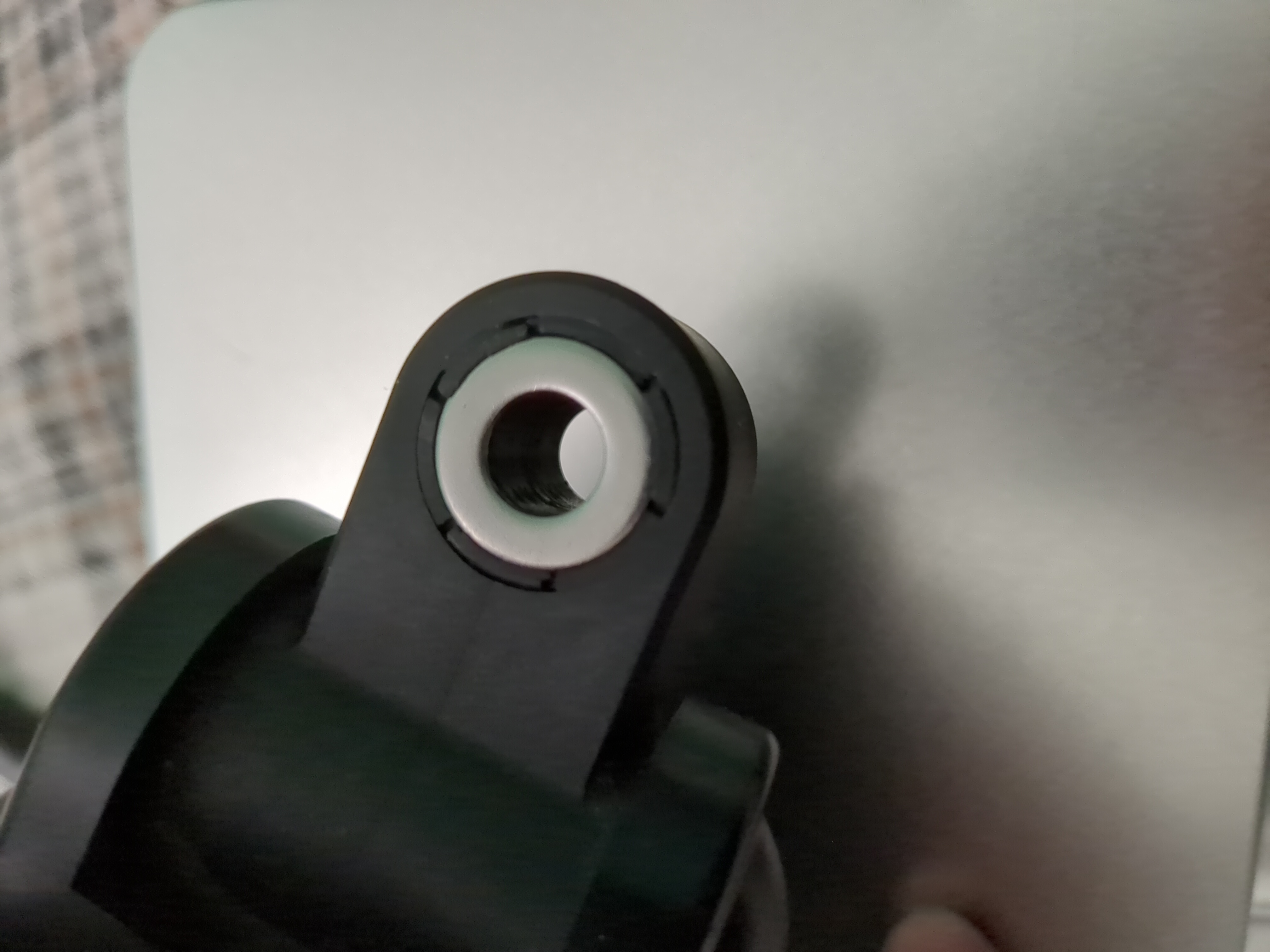
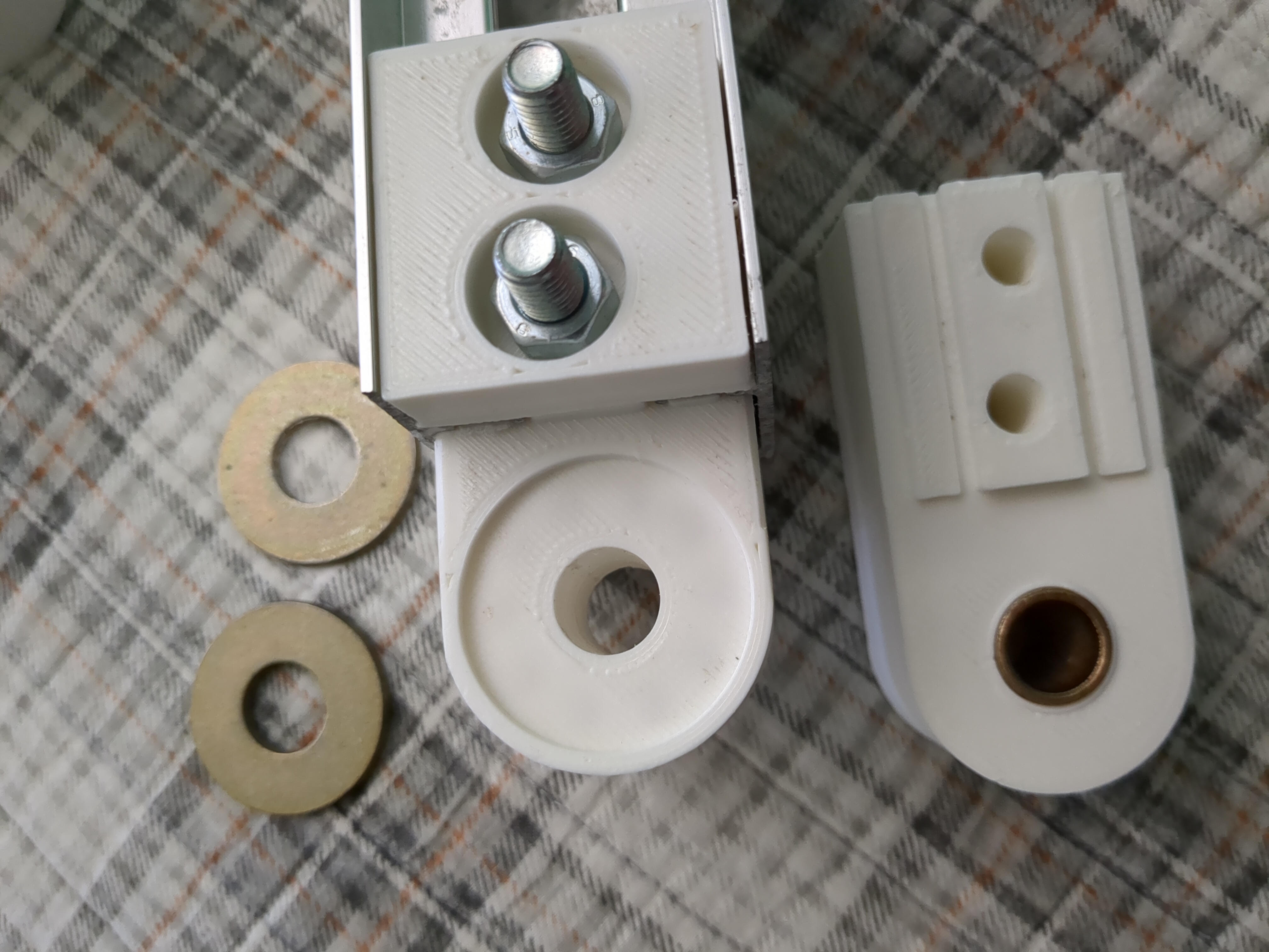
Like this joint has a recess in the top and bottom for washers with a bolt passing through the middle. It may seem like the bolt through the middle would be what holds the load and any slop in the joint, but this is not the case. The bolt is only holding the compression of the assembly and it is the gap between the washers that controls the slop and weight. It took me a few iterations to imitate this type of joint with a print.

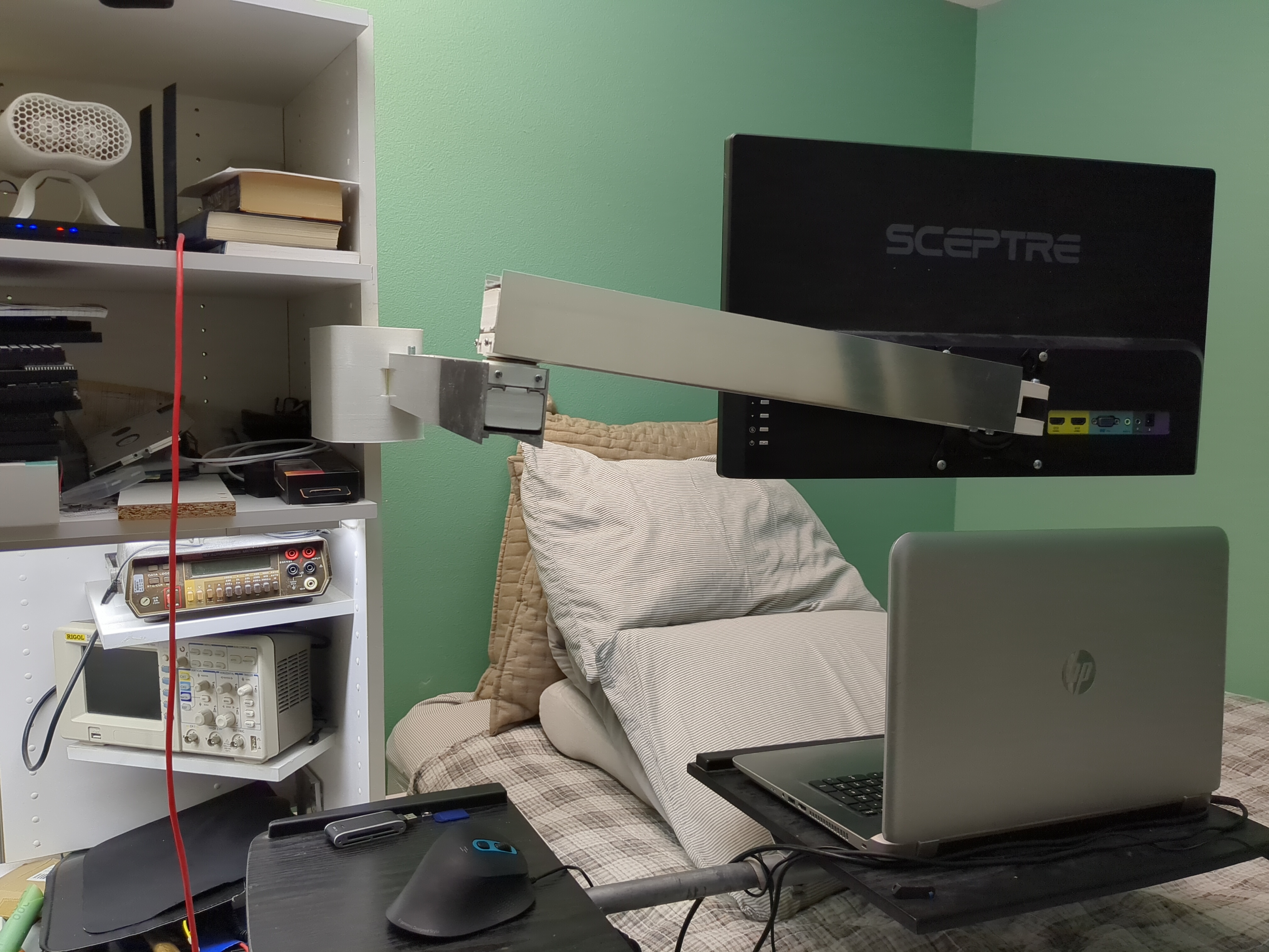
Ultimately, that arm needs another iteration to make it even more rigid, but it is usable like this. That arm is almost 5ft long with a 24in monitor on it.
That’s pretty cool! I had no idea about those structural voids